3.7.3.4 Stabilisation scenarios and their implications for futureCO2
emissions
Stabilisation scenarios illustrate implied rates of CO2 emission
that would arrive at various stable CO2 concentration levels. These
have been projected using a similar methodology to that applied in the analysis
of emissions scenarios. The WRE trajectories follow CO2 concentrations
consistent with the IS92a scenario beginning in 1990 and branch off to reach
constant CO2 concentrations of 450, 550, 650, 750 and 1,000 ppm (Wigley
et al., 1996). The rationale for various alternative time trajectories and stabilisation
levels is discussed in Chapter 2 of the IPCC WGIII Third
Assessment Report (Morita et al., 2001). Differences in emissions pathways for
different time trajectories leading to a certain stabilisation target (e.g.,
S versus WRE profiles) are discussed in Schimel et al., (1997). Here, we have
calculated emissions for one set of emission profiles to illustrate differences
in implied emissions that arise from updating models since the SAR.
As in Section 3.7.3.2, the models were initialised up
to present. Then anthropogenic emissions for the prescribed CO2 stabilization
profiles were calculated; deduced emissions equal the change in modeled ocean
and terrestrial carbon inventories plus the prescribed change in atmospheric
CO2 content. To estimate the strength of carbon cycle-climate feedbacks,
global temperature (ISAM) and changes in the fields of temperature, precipitation
and cloud cover (Bern-CC) were projected from CO2 radiative forcing
only, neglecting effects of other greenhouse gases and aerosols which are not
specified in the WRE profiles. The results for the reference cases are not substantially
different from those presented in the SAR (Figure 3.13).
However, the range based on alternative model parametrizations is larger than
presented in the SAR, mainly due to the range of simulated terrestrial CO2
uptake. CO2 stabilisation at 450, 650 or 1,000ppm would require global
anthropogenic CO2 emissions to drop below 1990 levels, within a few
decades, about a century, or about two centuries, respectively.
In all cases, once CO2 concentration becomes constant, the implied
anthropogenic emission declines steadily. This result was expected. It highlights
the fact that to maintain a constant future CO2 concentration, anthropogenic
CO2 emissions would ultimately have to be reduced to the level of
persistent natural sinks. Persistent terrestrial sinks are not well quantified;
peatlands may be a candidate, but the gradual rise in atmospheric CO2
concentration during the present interglacial (Figure
3.2) argues against any such sink. Estimates of current uptake by peatlands
are <0.1 PgC/yr (Clymo et al., 1998). Mixing of ocean DIC between surface
and deep waters should continue to produce ocean uptake for several centuries
after an input of anthropogenic atmospheric CO2 (Siegenthaler and
Oeschger, 1978; Maier-Reimer and Hasselmann, 1987; Sarmiento et al., 1992).
This mixing is the main reason for continued uptake (and therefore positive
calculated emissions) after stabilisation. However, the main, known natural
sink expected to persist longer than a few centuries is that due to dissolution
of CaCO3 in ocean sediments, which increases ocean alkalinity and
thereby allows additional CO2 to dissolve in the ocean. For CO2
concentrations about 1,000 ppm, this sink is estimated to be smaller than about
-0.1 PgC/yr (Archer et al., 1998). Thus, for any significant CO2
emissions to persist over centuries without continuing to increase atmospheric
CO2 would require some method of producing an artificial carbon sink.
|
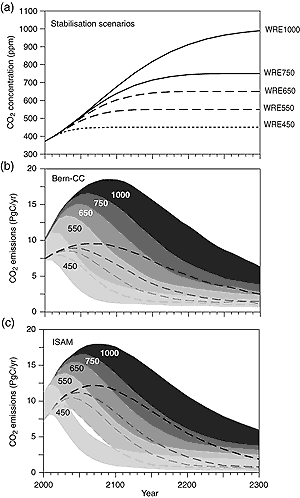
Figure 3.13: Projected CO2 emissions leading to stabilisation
of atmospheric CO2 concentrations at different final values.
Panel (a) shows the assumed trajectories of CO2 concentration
(WRE scenarios; Wigley et al., 1996) and panels (b) and (c) show the implied
CO2 emissions, as projected with two fast carbon cycle models,
Bern-CC and ISAM (see Box 3.7 and Figure
3.11). The ranges represent effects of different model parametrizations
and assumptions as indicated in the text and in the caption to Figure
3.11. For each model, the upper and lower bounds (corresponding to
low- and high-CO2 parametrizations, respectively) are indicated
by the top and bottom of the shaded area. Alternatively, the lower bound
(where hidden) is indicated by a dashed line.
|
|